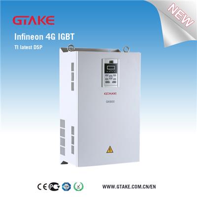
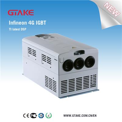
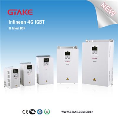
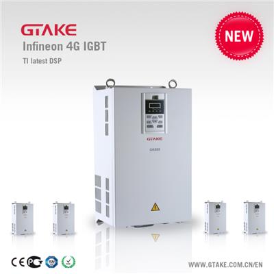
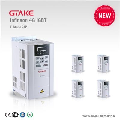
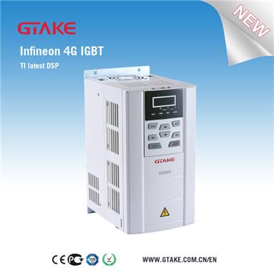
GK800Z Frequency Inverter For Sync Injection Molding Machine


GK800Z AC Motor Drives for Sync Injection Molding Machine
GTAKE GK800Z Series Electro-hydraulic Servo Drives are dedicated AC Motor Drives for Synchronous Injection Molding Machine with dedicated expansion board EPC-PG4 available.
1. Product Model and Technical Data
Drive Model
Power Level(kW)
Output Current (A)
Input Current (A)
Applicable Motor (kW)
Braking Unit
GK800Z-4T1.5B
1.5
3.8
6.2
1.5
Standard built-in
GK800Z-4T2.2B
2.2
5.5
9.2
2.2
GK800Z-4T3.7B
3.7
9
14.9
3.7
GK800Z-4T5.5B
5.5
13
21.5
5.5
GK800Z-4T7.5B
7.5
17
27.9
7.5
GK800Z-4T11B
11
24
39
11
GK800Z-4T15B
15
30
50.3
15
GK800Z-4T18.5B
18.5
39
60
18.5
GK800Z-4T22B
22
45
69.3
22
GK800Z-4T30B
30
60
86
30
GK800Z-4T37B
37
75
104
37
GK800Z-4T45B
45
91
124
45
GK800Z-4T55B
55
112
150
55
GK800Z-4T75B
75
150
201
75
GK800Z-4T90
90
176
160*
90
External
GK800Z-4T110
110
210
192*
110
GK800Z-4T132
132
253
232*
132
GK800Z-4T160
160
310
285*
160
GK800Z-4T185
185
350
326*
185
GK800Z-4T200
200
380
354*
200
GK800Z-4T220
220
430
403*
220
GK800Z-4T250
250
470
441*
250
GK800Z-4T280
280
520
489*
280
GK800Z-4T315
315
590
571*
315
GK800Z-4T355
355
650
624*
355
GK800Z-4T400
400
725
699*
400
* The input current after the direct current reactor is equipped,Website:, equip the external direct current reactor when the products of GK800Z-4T90 and above leave the factory. Please connect the electric reactor for use; otherwise the product will not work normally.
2. Technical Specification of GK800-Z AC Motor Drives
Power input
Rated voltage
3- phase AC380V/AC400V/AC415V/AC440V/AC460V/AC480V
Rated input current
Please see section 2.3
Frequency
50Hz/60Hz with the fluctuation range of ±5%
Allowable voltage range
Continuous voltage fluctuation of ±10%, transit fluctuation of -15%~+10%, i.e. 323V~528V;
Voltage unbalance rate <3% and the distortion rate meets the requirement of IEC61800-2.
Power output
Standard application motor (kW)
Please see section 2.3
Rated current (A)
Please see section 2.3
Output voltage(V)
3-phase: 0~rated output voltage and the error is less than ±3%
Output frequency (Hz)
0.00~600.00Hz, with the unit of 0.01Hz
Overload capacity
150% 1min
180% 10s
200% 0.5s
Running control characteristics
Control pattern
V/f control
Sensor-less vector control 1
Sensor-less vector control 2
Close-loop vector control
Range of speed regulation
1:100 (V/f control and sensor-less vector control 1
1:200 (sensor-less vector control 2)
1:1000(Close-loop vector control)
Speed control precision
±0.5% (V/f control)
±0.2% (sensor-less vector control 1 and 2)
±0.02%(Close-loop vector control)
Speed fluctuation
±0.3% (sensor-less vector control 1 and 2)
±0.1% (Close-loop vector control)
Torque response
<10ms(sensor-less vector control 1 and 2)
<5ms (Close-loop vector control)
Torque control precision
±7.5%(sensor-less vector control 2)
±5%(Close-loop vector control)
Start the torque
0.5Hz:180%(V/f control and sensor-less vector control 1 and 2)
0.25Hz:180%(sensor-less vector control 2)
0Hz:200%(Close-loop vector control)
Basic functions
Start frequency
0.00~600.00Hz
Accel/Decel time
0.00~60,000s
Carrier frequency
0.7kHz~16kHz
Frequency setting mode
Digital setting +Keypad∧/∨
Digital setting +terminal UP/DOWN setting
Communication setting
Analog setting (AI1/AI2/AI3)
Terminal pulse setting
Start-up mode
Started from starting frequency
DC braking then started
Speed search started
Halt mode
Slow down to stop
Coast to stop
Slow down to stop+ DC braking
Dynamic braking capacity
Operation voltage of the brake unit: 650V~750V; service time: 0.0~100.0s
DC braking capacity
Starting frequency of the DC braking: 0.00~600.00Hz DC braking current: 0.0~100.0% DC braking time: 0.0~30.00s
Input terminal
7 digital input terminals and one of them can be used for the high-speed pulse input. The open collectors NPN, PNP and dry contact input mode are compatible.
3 analog input terminals and one of them can be only used for the voltage input and two voltages and current can be selected.
Output terminal
1 high-speed pulse output terminal, 0~50kHz square signal output and the output of the physical quantities such as the frequency setting, output frequency etc. can be achieved.
1 digital output terminal
2 groups of relay output terminals
2 analog output terminals, the voltage and current can be selected and the output of the physical quantities such as the frequency setting, output frequency etc. can be achieved.
Coder signal terminal
Compatible with the coder with the voltage of 5V/12V
Compatible with the coder signal input of different forms such as the open collector, push-pull, difference etc.
Protection function
Please refer to Chapter 7 – Troubleshooting and Abnormity Handling
Environment
Place of operation
Indoors, no direct sunlight, free from dust, corrosive gases, flammable gases, oil mist, water vapor, water drop and salt etc.
Altitude
0~2,000m 1% of the rated output current is de-rated for rising each 100m when the altitude is above 1,000m
Ambient temperature
De-rating between -10℃~40℃ and 40℃~50℃ for each raised 1℃ and the rated output current is deduced1%
humidity
5~95%, no condensation
Vibration
Less than 5.9 m/s2 (0.6g)
Storage temperature
-40℃~+70℃
Others
Efficiency
Rated power is 7.5kW and below: ≥93% 11~45kW: ≥95% 55kW and above: ≥98%
Installation mode
Wall mounted
Protection level
IP20
Cooling mode
Force air cooling
3. Control Panel Diagram of GK800-Z AC Motor Drives
4. Standard Wiring Diagram of GK800-Z AC Motor Drives
Fig. 4 Standard Wiring Diagram
5. Functional Specification of the Control Terminal
Table 4 Functional Specification of the Control Terminal
Category
Terminal symbol
Terminal name
Technical specification
Analog input
+10V
Analog input reference voltage
10.3V ±3%
Maximum output current 25mA
The resistance of external potentiometer should be greater than 400Ω
GND
Analog ground
Isolated from COM interiorly
AI1
Analog input 1
0~20mA: input impedance - 500Ω, maximum input current - 25mA
0~10V: input impedance - 100kΩ, maximum input voltage - 12.5V
Switch S2 for jumping from 0~20mA and 0~10V, factory default voltage input
AI2
Analog input 2
0~20mA: input impedance - 500Ω, maximum input current - 25mA
0~10V: input impedance - 100kΩ, maximum input voltage - 12.5V
Switch S3 for jumping from 0~20mA and 0~10V, factory default voltage input
Toggle switch S4 can realize analog input of direct detection of motor temperature
AI3
Analog input 3
-10V~10V: input impedance: 25kΩ
Maximum range of input voltage: -12.5V~+12.5V
Analog output
AO1
Analog output 1
0~20mA: impedance: 200Ω~500Ω
0~10V: impedance ≥ 10kΩ
Switch S5 for jumping from 0~20mA and 0~10V, factory default voltage output
AO2
Analog output 2
0~20mA: impedance: 200Ω~500Ω
0~10V: impedance≥10kΩ
Switch S6 for jumping from 0~20mA and 0~10V, factory default voltage output
GND
Analog ground
Isolated from COM interiorly
Digital input
+24V
+24V
24V±10%, isolated from GND interiorly
Maximum load: 200mA
PLC
Digital input Common terminal
Used for switching between high and low levels, short-circuited with +24V at delivery, i.e. low value of digital input valid
External power input
COM
+24V ground
Isolated from GND interiorly
X1~X6
Digital input Terminals 1~6
Input specification: 24VDC, 5mA
Range of frequency: 0~200Hz
Range of voltage: 10V~30V
X7/DI
Digital input/pulse input
Digital input: same as X1~X6
Pulse input: 0.1Hz~50kHz; range of voltage:10-30V
Digital output
Y1
Open collector output
Range of voltage: 0~24V
Range of current: 0~50mA
Y2/DO
Open collector output/Pulse output
Open collector output: same as Y1
Pulse output: 0~50kHz
Relay 1 output
RA/RB/RC
Relay output
RA-RB: NC
RA-RC: NO
Contact capacity: 250VAC/3A, 30VDC/3A
Relay 2 output
TA/TB/TC
Relay output
TA−TB: NC
TA−TC: NO
Contact capacity: 250VAC/3A, 30VDC/3A
Encoder signal input
VCC
Encoder power supply
Select power supply 5V/12V for encoder by S7
COM
Encoder power ground
Isolated from GND interiorly
A+
Phase input A+
Select differential/OC input mode by S7.
In OC mode, this terminal is not connected
A-
Phase input A-
Select differential/OC input mode by S7.
In OC mode, this terminal is directly connected to phase A signal of the encoder
B+
Phase input B+
Select differential/OC input mode by S7.
In OC mode, this terminal is not connected
B-
Phase input B-
Select differential/OC input mode by S7.
In OC mode, this terminal is directly connected to phase B signal of the encoder
Terminal 485 Interface
485+
Differential signal 485+
Rate: 4,800/9,600/19,200/38,400/57,600/115,200bps
485−
Differential signal 485-
Maximum distance: 500m (use standard network cable)
Keypad 485 interface
GND
485 Communication shielded ground
Isolated from COM interiorly
CN4
Keypad 485 interface
The Keypad can be introduced from other localities and the introduced cable must use the standard network cable.
6.Our Services
In the trend of advocating smart and simple industrial automation, environmentally friendly products, value-added solutions, GTAKE as one of the world's leading Frequency Inverter manufacturers aggressively investing in R&D, production, and continuous quality improvement, is well positioned to provide its customers with technology-driven, performance-outstanding products such as Frequency Inverters, wind power converters, servo drives, HEV/EV motor controllers, helping its customers save energy and increase industrial productivity with sustainability on the one hand, and enhancing their entire value-chain quality, delivery, and services on the other hand.
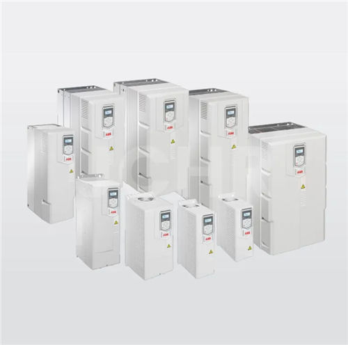
7.Comparison of GTAKE brand AC Motor Drives and other common brands
Other supplier products
All supplier products
Same products