Flexible Waveguide


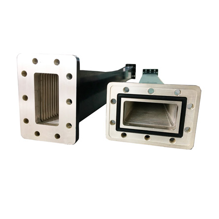
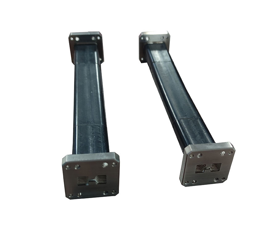
As one of the most professional flexible waveguide manufacturers, Dolph Microwave manufactures a quality line of flexible twistable/non-twistable waveguides, specially designed to meet all of your requirements. The components is made from a helically wound waveguide core and additional mechanical support is offered from a variety of protective jackets.
Flexible waveguide definition
The Flexible Waveguide is parts of Feeder line, compared with the rigid waveguide, which is not only reduces the difficulty of connection, but also keep connection accuracy. The Rectangular Flexible Waveguide has E bend and H bend function including twisted function.
Flexible Waveguide Ordering Guide
Flexible Twistable Waveguide Ordering Information
Ordering Information of Flexible Twistable Waveguide
Flexible Non-twistable Waveguide Ordering Information
Ordering Information of Flexible Non-twistable Waveguide
Flange type: Multiple types available - see Dolph Microwave Flanges page.
Flexible Waveguide Datasheet
ELECTRICAL SPECIFICATIONS
Waveguide Designation Freq.Range
(GHz) Insertion
Loss(dB/m) Suggested Power Limit Return Loss (dB)
Peak(MW) Average(KW) 300mm 600mm 900mm 1000mm 1200mm 1500mm 1800mm
R40 WR229 WG11A 3.22-4.90 0.15 1.6 5 31.0 28.8 28.3 28.3 27.8 27.3 26.3
R48 WR187 WG12 3.94-5.99 0.16 1.4 3 31 28.8 28.3 28.3 26.4 23.1 21.7
R58 WR159 WG13 4.64-7.05 0.18 0.6 2.5 31 28.3 27.8 27.8 26.4 23.1 21.7
R70 WR137 WG14 5.38-8.17 0.25 0.56 2 30.2 27.8 27.3 27.3 26.4 23.1 21.7
R84 WR112 WG15 6.57-9.99 0.3 0.33 1.5 30.2 27.3 27.1 27.1 26.4 23.1 21.7
R100 WR90 WG16 8.20-12.5 0.4 0.22 1 30.2 27.1 27 27 25.2 22.1 19.7
R120 WR75 WG17 9.84-15 0.5 0.18 0.75 29.4 27 26.4 26.4 24 20.93 19.7
R140 WR62 WG18 11.9-18 0.65 0.12 0.4 29.4 26.4 26 26 24 20.93 19.7
R220 WR42 WG20 17.7-26.5 1.2 0.045 0.1 23 22.1 21.1 21.1 - - -
R320 WR28 WG22 26.5-40 2 0.022 0.075 21 20.8 20.8 20.8 - - -
R400 WR22 WG23 33-50 2.5 - - 20 16.5 15.6 16 - - -
MECHANICAL SPECIFICATIONS
Waveguide Designation Max Twist(Deg/m) Min E-Bending Radii(mm) Min H-Bending Radii(mm)
Static Repeated Static Repeated Static Repeated
R40 WR229 WG11A 132 33 165 660 330 1320
R48 WR187 WG12 155 40 136 544 272 1088
R58 WR159 WG13 185 45 116 464 232 928
R70 WR137 WG14 210 52 100 400 200 800
R84 WR112 WG15 260 68 82 328 164 656
R100 WR90 WG16 315 76 66 264 132 528
R120 WR75 WG17 365 92 54 216 108 432
R140 WR62 WG18 445 112 46 184 92 368
R220 WR42 WG20 630 157 30 120 60 240
R320 WR28 WG22 920 230 20 80 40 160
R400 WR22 WG23 920 230 18 78 38 158
*The Standard Model Numbers above are the most common parts ordered for size, material and flange. However, these models can easily be altered to accommodate your needs by using the Model # code system below for complete part number.
** Please refer to the Technical Reference section for flange types/connectors details. Please contact us for your specific requirements.
Flexible Waveguide Diagram
Flexible waveguide use mechanically and electrically interlinked metallic structures to form a hollow channel that behaves as a waveguided with enhanced flexible and somewhat reduced performance. As the interlinked metallic structures, even if soldered and crimped, are not perfectly smooth conductive walls, the performance of flexible waveguides will not likely reach that of a traditionally manufactured waveguide. That being said, the flexible nature of these waveguide allows them to be used in applications for which rigid waveguide structures may be too bulky, unfit for the complexity of the geometries, too heavy, take too long to design/assemble, or may be unavailable during emergency repairs or retrofitting operations.
Flexible Waveguide Options
Flexible Waveguide Type: Twistable or non-twistable.
FlexibleWaveguide Size: WR137, WR112, WR90, WR75 or others.
Insertion Loss and VSWR: unit in dB.
Flexible Waveguide Length: 300, 500, 900, 1200, 1800 or other length in mm.
Flange type: Flat or groove or chock.
Hardware kits: Required or self preparation.
Any special requirement, please offer the drawing or dimension for checking.
Flexible Waveguide Usage
Flexible Waveguide Usage
Flexible waveguide normally is for connecting different kinds of two components. Flexible waveguide is often together used with rigid waveguide systems especially if it cannot be located or positioned well. Flexible waveguide advantages offered is well outweigh the electrical performance limitations which is easy for flange and waveguide port change position. In other words is allow for mechanical movement.
Flexible Waveguide Benefits
Flexible waveguide are used in virtually every application that rigid waveguide are used, with the exception of extremely high power, low loss, or certain mechanical stresses are common. Waveguide systems that may require a range of adjustments, such as with satellite positioning systems, are likely to employ flexible waveguide. The bendable, and sometimes even bend/twist, nature of flex waveguide can reduce installation difficulties from misalignments common in system installation, repair, retrofitting. Flexible waveguides can also be used to isolate different sections of waveguide and mechanical structures from vibration and shock, which a rigid waveguide interconnect would not be able to do. Lastly, a flexible waveguide could be used in structures that are likely to shift or produce relative movement during thermal cycles, movement, or intense weather.
Benefits
For use in High Power Applications
Finished with high temperature paint
VSWR as low
Insertion loss
Flexible and durable neoprene sleeve
Flexible Waveguide Applications
Flexible waveguide for satellite applications and other airborne and space systems include seamless flexible waveguide, flexible twistable waveguide, flexible waveguide, and semi flexible waveguide.
Flexible and twistable rectangular waveguides are used in a wide variety of Satcom, VSAT and telecom applications that carry high frequency radio.
Flexible waveguide is often used to connect two elements using rigid waveguide systems together, especially when they cannot be accurately located or positioned.. For example, flexible waveguide is often used to connect antenna systems, especially when they may not be fixed, to the base transmitter receiver system.
Other Standard Waveguide Components You may have interests in
waveguide pressure inlet
waveguide attenuator types
different types of waveguide attenuators
waveguide quick disconnect
magic tee in microwave engineering
waveguide o ring
coupling probes
Flexible Waveguide Construction
Flexible waveguide is available in a variety of different forms. Each type has its own advantages and disadvantages:
Flexible and Twistable
Flexible twistable is sealed electrically via a friction joint. This construction has the best twistable performance of all flexguides.
Flexible Waveguide
Flexible Waveguide core is wound with a solder fillet in the Interlock, thus eliminating any RF and Pressure Leakage. Flexible Waveguide will flex in the E and H planes, although pre-set twists can be incorporated during manufacture.
Flexible Seamless
Flexible/seamless offers a solution to problems where pressurization is required. It has no solder joints and therefore can easily hold pressure.
Made from helically wound silver plated brass strip
The flexible waveguide may be made from flat ribbons would on a rectangular mandrel. The edges are then convoluted or folded in and interlocked. The convoluted flexible waveguide may be left unsoldered or it may be soldered - the flexibility of the waveguide results from the flexing of each arm and not the relative sliding of the ribbons. However if it is soldered it does loose some flexibility and it is not able to be twisted to any degree.
A form of corrugated flexible waveguide may be constructed. It is manufactured by shaping thin wall rectangular tubing. It may also be made by bending and soldering corrugated sheet metal.
It is also possible to construct a bellows-style flexible waveguide using a flexible alloy.
Another common form of flexible waveguide construction is to use a helically wound system. This form of flexible waveguide is manufactured by a process of helical winding a silver coated, brass strip to form a continuous, uniform rectangular tube.
In general, flexible waveguide is jacketed in Neoprene, Silicone, Viton, Devcon or other similar materials to provide additional protection from mechanical damage while still allowing flexibility.
Why Choose Dolph Microwave As Your Flexible Waveguide Manufacturer?
Great Design
We can design UG-style square/round cover and CPR-style flanges specifically for each customer requirement.
Accuracy
Precision machining ensures accurate and lasting performance.
Customization Accepted
Flexible waveguide can be customized as per customer requirements.
Quantity Storage
Dolph Microwave flexible waveguides are in stock and ready for immediate shipment with no minimum order quantity.
Other supplier products
|
|
Double Ridged Flexible Waveguide |
Flexible waveguide products can be divided into flexible waveguide (interlocked flexible waveguide) and non-twisting flexible waveguide (seamless f... |
|
|
INDUSTRIAL MICROWAVE COMPONENTS |
Dolph Microwave offers a full line of industrial microwave products. Specializing in waveguide components, including launchers, isolators, directio... |
|
|
Industrial Microwave Magnetron WG Launcher |
Dolph Microwave produces waveguide components for both high-end and simple microwave plasma applications. Microwave components for industry microwa... |
|
|
Waveguide Couplers |
Dolph Microwave manufactures Waveguide Directional Couplers covering a wide frequency range from WR2300 to WR10. Couplers are available in 3 or 4 p... |
|
|
WAVEGUIDE COMPONENTS |
Dolph Microwave R&D and manufactures various of standard waveguide component, double ridged waveguide components, industrial microwave componen... |
All supplier products
Same products


