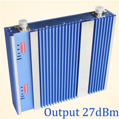
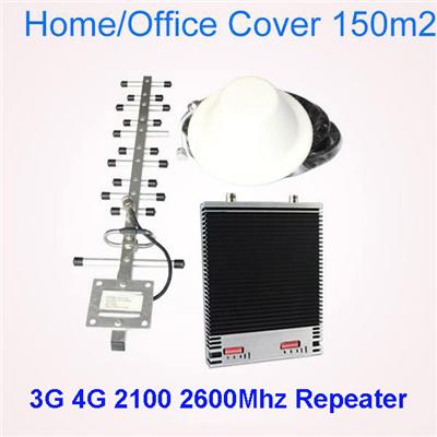
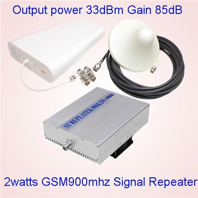
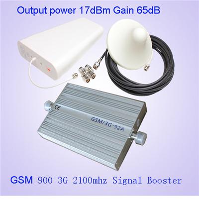
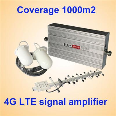
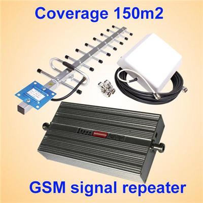
24dBm 850 1900 Dual Band Signal Booster MGC AGC ALC


HPC-CP-27A CDMA850 and PCS1900mhz Dual band signal repeaters
Product introduction
Mobile signal booster is designed to enhance the indoor mobile signal. The main reason leads to the weak indoor signal is the rebar inside of the concrete walls. Because the rebar will absorb and isolate the wireless signals.
This product can amplify the wireless signals by special outdoor antenna and signal process circuits. The mobile signals will be transmitted into indoor space again after being magnified. The indoor signal would be enhanced because it will not be absorbed by the rebar concrete.
Features:
Light weight,Website:, compact size and high performance.
Provides a quick cost effective solution to indoor coverage problems.
Reduces dropped calls.
High linear design, low interference to the BTS.
Low power consumption, ease of installtion and great coverage.
Intelligent design with built in ALC function, ATT manual attenuation control at 1db/steps.
With proper installation, expected coverage is 100~1500m².
Reduces cell radiation and extends cell battery life.
Description
HPC-CP-27A Dual band repeater is to support any two mobile band existing in the world to help end users to improve mobile signals for much better call quality and smoother data transmission. It is designed to support coverage area up to 100-2000 square meters with proper engineering. Below are the main features.
1.The consumer repeater is an ideal solution for providing a cost effective improvement in cellular in-building coverage of a home, office, restaurant or building, in the quickest time possible.
2.Manual gain control (MGC) available for both uplink and downlink to adjust the gain value for proper coverage during installation or maintenance.
3.To maintain safe and specific output signal levels and give alarms on self-oscillation, the repeater has built-in AGC and ALC circuits, which can automatically control the gain of the repeater depending upon the strength of input signals.
4.Auto shut off function available for both uplink and downlink to avoid deep self-oscilation from jamming the towers, saving your trouble from operators.
5.Wide band feature enables all devices operating within the wide frequency range of the repeater to see an improvement in performance.
6.Multiple s and other handheld devices throughout a building can benefit from a wireless repeater.
7.Supports up to (180) users / calls simultaneously.
8.Extended battery life. (Your does not need to put out as much power due to improved reception.)
Specification:
Electrical specification
Uplink
Downlink
Frequency Range
CDMA
824-849 MHz
869-894 MHz
PCS
1850-1910 MHz
1930-1990 MHz
Max .Gain
≥ 75dB
≥ 75dB
Max .Output Power
≥ 27dBm
≥ 27dBm
Band width (-3dB)
Wide Band
MGC ( Step Attenuation )
≥ 31dB / 1dB step
Automatic Level Control
≥ 15dB, auto shut off after 15dB
Gain Flatness
GSM & CDMA
Tpy≤ 6dB(P-P); DCS,PCS ≤ 8dB(P-P)
WCDMA
≤ 2dB/ 3.84MHz,Full Band ≤ 5dB(P-P)
Noise Figure
≤ 8dB
VSWR
≤ 2.0
Group Delay
≤ 1.5μs
Frequency stability
≤ 0.01ppm
Spurious Emission & Output inter-modulation
GSM Meet ETSI TS 151 026 V 6.1.0
WCDMA Meet 3GPP TS 25.143 ( V 6.2.0 )
CDMA Meet IS95 & CDMA2000
WCDMA System
Spurious Emission Mask
Meet 3GPP TS 25.143 ( V 6.2.0 )
Modulation Accuracy
≤ 12.5%
Peak Code Domain Error
≤ -35dB@Spreading Factor 256
CDMA System
Rho
ρ > 0.980
ACPR
Meet IS95 & CDMA2000
Mechanical Specifications
Standard
I /O Port
N-Female
Impedance
50 ohm
Operating Temperature
-25ºC ~+55ºC
Environment Conditions
IP40
Dimensions
250x330x53mm
Weight
≤ 4.5Kg
Power Supply
Input AC90~264V,output DC12V / 5A
LED Alarm
Standard
Power LED
Power Indicator
ALC LED 1 (Low frequency Band)
Orange @ ALC 1~5dB, Red @ ALC 15dB~20dB,
LED off after 5 seconds red color
ALC LED 2 (Middle frequency Band)
Orange @ ALC 1~5dB, Red @ ALC 15dB~20dB,
LED off after 5 seconds red color
ALC LED 3 (High frequency Band)
Orange @ ALC 1~5dB, Red @ ALC 15dB~20dB,
LED off after 5 seconds red color
The installtion of the Repeater
Outdoor antenna ( for receiving the signal from the BTS ) + Cable ( transfering the received signal) + Repeater ( for amplifying the received signal) + cable( for transfering the amplified signal) + indoor antenna( for shooting the amplified signal),
Installation steps
Step 1 Start by taking your up to the roof or other location outside to find where the signal is strongest.
Step 2 Temporarily mount the Outdoor (outside) antenna in that location. You may need to adjust and move the antenna later.
Step 3 Run coaxial cable into the building to a convenient loaction (attic, etc.) where you can also get standard power for the Signal Repeater.
Step 4 Place the Signal Repeater in that location and connect the coaxial cable to the Outdoor Side of the Signal Repeater and the Outdoor antenna.
Step 5 Mount your Indoor (inside) antenna in a productive location. You may need to adjust or move the antenna later. More notes on Indoor antennas and patterns here.
Step 6 Connect coaxial cable between the Indoor antenna and the Signal Repeater output port.
Step 7 Power up the system and check for signal inside the building. If needed, tune system by moving and or pointing the Outdoor and Indoor antennas until they get the most signal possible.
Step 8 Secure all antennas and cables, securely mount the Signal repeater and clean up the installation.
Of course there are still a few more things to consider but in general, this is the basic procedure. For more information, please contact us.
Terms and Conditions
Certificate
CE/RoHs
Country of Origin
China
Port of Dispatch
Shenzhen
Production Capacity
1000pcs/month
Date of Delivery
Within 3 days after received payment inform
MOQ
10pcs
Warranty
2years
Pacakge
1pcs/box; 5pcs/carton
Country of Origin
China
Other supplier products
All supplier products
Same products


