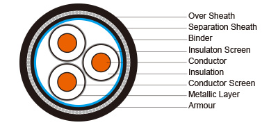
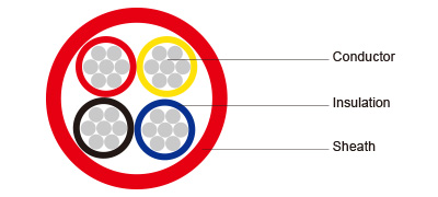
Three Core Cables To BS 6622


Three Core Medium Power Cable to BS 6622
Application:
The three core cables are designed for distribution of electrical power with nominal voltage Uo/U ranging from 3.6/6.6KV to 19/33KV and frequency 50Hz. They are suitable for installation mostly in power supply stations,Website:, indoors and in cable ducts, outdoors, underground and in water as well as for installation on cable trays for industries, switchboards and power stations.
Standards:
BS 6622
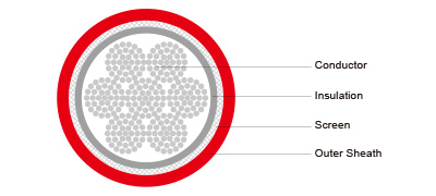
Conductor:
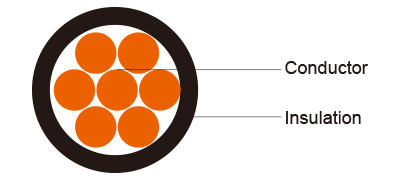
Plain annealed copper or aluminium complying with IEC 60228/BS 6360. Copper conductors shall be stranded (class 2) and aluminium conductors shall be either solid or stranded (class 2).
Conductor Screen:
Extruded layer of semi-conducting cross-linkable compound is applied over the conductor and shall cover the surface completely. The minimum thickness is 0.3mm and the maximum resistivity shall not exceed 500 Ohm-m at 90℃
Insulation:
Insulation is of cross-linked polyethylene compound XLPE (GP8) conforming to BS 7655-1.3 or EPR (GP7), conforming to BS 7655-1.2.
Table 1. Insulation Thickness
Nom. Cross Section Area
Insulation Thickness at Nom. Voltage
3.8/6.6KV(Um=7.2KV)
6.35/11KV(Um=12KV)
8.7/15KV(Um=17.5KV)
12.7/22KV(Um=24KV)
19/33KV(Um=36KV)
mm²
mm
mm
mm
mm
mm
70 – 185
2.5
3.4
4.5
5.5
8.0
240
2.6
3.4
4.5
5.5
8.0
300
2.8
3.4
4.5
5.5
8.0
400
3.0
3.4
4.5
5.5
8.0
Above 500
3.2
3.4
4.5
5.5
8.0
Insulaton Screen: Extruded layer of semi-conducting cross-linkable compound is applied over the insulation. The extruded semi-conducting layer shall consist of bonded or cold strippable semi-conducting compound capable of removal for jointing or terminating. As an option, a semi -conducting tape may be applied over the extruded semi-conducting layer as a bedding for the metallic layer. The minimum thickness is 0.3 mm and the maximum resistivity is 500 Ohm-m at 90°C. The screen is tightly fitted to the insulation to exclude all air voids and can be easily hand stripped on site. Inner Covering & Fillers: For cables with a collective metallic layer or cables with a metallic layer over each individual cores with additional collective metallic layers, semi-conducting inner covering and fillers shall be applied over the laid up cores. The inner covering is made of non hygroscopic material, except if the cable is to be made longitudinally watertight. The inner covering shall be extruded or lapped. The approximate thickness of extruded inner coverings is given in Table 2: Table 2. Approximate Thickness Of Extruded Inner Coverings
Ficititous Diameter Over Laid Up Cores
Approx. Thickress of Extruded Inner Covering
mm
mm
>
<< p=""><
35
45
1.0
25
35
1.2
35
45
1.4
45
60
1.6
60
80
1.8
80
-
2.0
*The approximate thickness of lapped inner coverings shall be 0.6mm.
Metallic Layer: The metallic layer shall be applied over each core or applied as a collective screen. The metallic screen shall consist of either copper tapes or a concentric layer of copper wires or a combination of tapes and wires. The metallic layer provides an earth fault current path, capable of withstanding fault current to earth of 1000A for one second at maximum temperature 160°C. Copper wires are applied over the conducting water blocking layer with a minimum diameter of 0.5mm. And over the copper wires, copper tape with minimum thickness of 0.1mm can be applied helically with overlap. Total cross section of copper wire screen is shown in table 3.
Table 3. Minimum Total Cross Section Of Copper Wire Screen & DC Resistance Of The Screen
Nominal Cross-Section Area of Cable
Minimum Cross-Section of Copper Wire Screen Area
DC Resistance of the Copper Wire Screen
mm²
mm²
mm
up to 120
16
1.06
150-300
25
0.72
400-630
35
0.51
Separation Sheath (for armoured cable): The separation sheath comprises a layer of extruded PVC, PE or LSZH. The nominal thickness is calculated by 0.02Du + 0.6mm where
Du is the fictitious diameter under the sheath in mm. The nominal separation sheath thickness shall not be less than 1.2mm. Armour (for armoured cable): The armour consists of galvanized steel wire applied over the inner covering with diameter specified as in Table 4.
Table 4. Armour Wire Diameter
Fictitiious Diameter Under the Armour
Armour Wire Diameter
mm
mm
>
<< p=""><
25
1.6
25
35
2.0
35
60
2.5
60
-
3.15
Over Sheath: Overall sheath comprises a layer of extruded either PVC type 9 conforming to BS 7665-4.2 or MDPE type TS2 conforming to BS 7655-10.1; LSZH can be offered as an option. The oversheath is normally black in colour. When a DC voltage test is to be performed on the oversheath, a semi-conducting layer such as graphite coating shall be applied over the surface of the extruded oversheath. The nominal oversheath thickness is calculated by 0.035+D where D is the diameter immediately under the oversheath in mm. For cables with the oversheath not applied over the armour, the nominal oversheath thickness shall not be less than 1.4mm. And for cables with oversheath applied over the armour, the nominal oversheath thickness shall not be less than 1.8mm. PHYSICAL PROPERTIES: Operating Temperature: up to 90°C Temperature Range: -5°C ( PVC sheath ); -20°C ( PE sheath ) Short Circuit Temperature: 250°C (short circuit duration up to 5 seconds) Bending Radius: 15 x OD Table 5. Nominal /Operating /Test Voltages
Rated Voltage Uo/U
Operating Voltage (Um)
Testing Voltage (rms)
3.8/6.6KV
7.2KV
15KV
6.35/11KV
12KV
25.5KV
8.7/15KV
17.5KV
35KV
12.7/22KV
24KV
51KV
19/33KV
36KV
76KV
hree Core 3.8/6.6KV (Um=7.2KV) Dimensional Data
Nom. Cross- Section Area
Unarmoured Cables
Steel Wire Armoured Cables
Nom.Insulation Thickness
Copper Tape Screen Area
Nom.Sheath Thickness
Approx. Overall Diameter
Approx. Weight
Copper Tape Screen Area
Nom.Bedding Thickness
Nom. Armour Wire Diameter
Nom.Sheath Thickness
Approx. Overall Diameter
Approx. Weight
CU
AL
CU
AL
mm2
mm
mm2
mm
mm
kg/km
mm2
mm
mm
mm
mm
kg / km
25
2.5
16
2.1
37.7
2205
1740
3.4
1.2
2.0
2.2
44.5
3890
3465
35
2.5
16
2.3
41.2
2690
2010
3.6
1.2
2.5
2.3
46.8
4420
3730
50
2.5
16
2.5
44.9
3340
2350
3.8
1.3
2.5
2.5
51.5
5640
4690
70
2.5
16
2.6
48.0
4050
2730
4.3
1.3
2.5
2.6
55.0
6570
5240
95
2.5
16
2.7
51.7
5000
3180
4.7
1.4
2.5
2.7
58.9
7760
5890
120
2.5
16
2.8
54.7
5890
3590
5.0
1.5
2.5
2.8
62.1
8810
6510
150
2.5
25
2.9
58.4
6960
4160
5.3
1.5
2.5
2.9
65.8
10110
7310
185
2.5
25
3.0
61.9
8160
4650
5.8
1.6
2.5
3.0
69.5
11520
7960
240
2.6
25
3.2
68.1
10210
5530
6.3
1.7
2.5
3.2
75.9
13920
9140
300
2.8
25
3.5
73.6
12380
6670
7.0
1.8
3.15
3.5
83.1
17400
11620
400
3.0
35
3.7
83.8
16190
8430
7.7
2.0
3.15
3.7
93.0
21900
13980
Electrical Data
Nom. Cross- Section Area
Unarmoured Cables
Steel Wire Armoured Cables
Current Ratings
D C Resistance CU / AL
A C Resistance CU / AL
Short Circuit Rating of Conductor CU / AL 1 sec
Capaci- tance
Charging Current
Short Circuit Rating of Copper Wire Screen Per Core 1 sec
Short Circuit Rating of Copper Tape Screen Per Core 1 sec
Reac-tance
Induc- tance
Ground
Duct
Air
CU
AL
CU
AL
CU
AL
mm2
μΩ/m
μΩ/m
kA
pF/m
mA/m
kA
kA
μΩ/m
nH/m
A
A
A
25
727/1200
927/1538
3.6/2.3
272
0.33
2.6
0.4
113
370
140
115
125
95
145
115
35
524/868
668/1113
5.0/3.2
301
0.36
2.6
0.5
108
350
170
135
150
115
175
140
50
387/641
494/822
6.8/4.4
332
0.40
2.6
0.5
102
330
210
160
180
135
220
170
70
268/443
343/568
9.8/6.3
383
0.46
2.6
0.6
97
310
255
195
215
165
270
210
95
193/320
248/410
13.3/8.5
432
0.52
2.6
0.6
92
290
300
230
255
200
330
250
120
153/253
196/325
17.2/11.0
474
0.57
2.6
0.7
89
280
340
265
290
225
375
295
150
124/206
159/265
21.2/13.5
511
0.61
4.3
0.7
87
280
380
295
330
255
430
330
185
99.1/164
128/211
26.6/17.0
562
0.67
4.3
0.8
86
270
430
335
370
290
490
385
240
75.4/125
98/161
34.9/22.3
602
0.72
4.3
0.9
83
260
490
380
425
335
570
450
300
60.1/100
80/130
43.8/28.0
622
0.75
4.3
1.0
82
260
540
435
470
375
650
510
400
47.0/77.8
64/102
57.3/36.6
648
0.78
5.8
1.1
80
250
590
480
520
420
700
570
Three Core 6.35/11KV (Um=12KV) Dimensional Data
Nom. Cross- Section Area
Unarmoured Cables
Steel Wire Armoured Cables
Nom. Insulation Thickness
Copper Wire Screen Area
Nom. Sheath Thickness
Approx. Overall Diameter
Approx. Weight
Copper Tape Screen Area
Nom. Bedding Thickness
Nom. Armour Wire Diameter
Nom. Sheath Thickness
Approx. Overall Diameter
Approx. Weight
CU
AL
CU
AL
mm2
mm
mm2
mm
mm
kg/km
mm2
mm
mm
mm
mm
kg / km
25
3.4
16
2.3
42.8
2600
2120
3.8
1.3
2.5
2.4
50.0
4930
4400
35
3.4
16
2.3
45.3
3000
2320
4.1
1.3
2.5
2.5
52.3
5380
4700
50
3.4
16
2.4
48.5
3630
2690
4.4
1.4
2.5
2.6
55.7
6210
5260
70
3.4
16
2.5
52.0
4440
3110
4.7
1.4
2.5
2.7
59.2
7200
5870
95
3.4
16
2.7
56.0
5440
3620
5.2
1.5
2.5
2.8
63.2
8420
6550
120
3.4
16
2.8
59.4
6370
4020
5.5
1.6
2.5
3.0
67.0
9580
7190
150
3.4
25
2.9
62.7
7430
4630
5.8
1.6
2.5
3.1
70.3
10830
8030
185
3.4
25
3.0
66.1
8680
5150
6.2
1.7
2.5
3.2
73.9
12290
8720
240
3.4
25
3.1
71.7
10690
5990
6.8
1.8
3.15
3.4
81.2
15620
10790
300
3.4
25
Other supplier products
|
|
|
450/750V LSZH Insulated (single core) Application:The cables is mainly used in power stations,Website:, mass transit underground passenger systems,... |
|
|
|
0.6/1kV HF-EPR Insulated,Website:, SW2/SW4 Sheathed Unarmoured Fire Resistant Power & Control CablesApplication:These fire resistant elastomeric in... |
|
|
|
Type SHD-PCG Three-Conductor Portable Power Cable 2kV ICEA S-75-381ApplicationsThese heavy duty cables are designed for use on longwall shearers,We... |
|
|
|
NTMCWOEU Flexible Medium-Voltage Single Core Cable VDE 0250 Part 813ApplicationsThese cables are used for connection in switch-gear and for connect... |
|
|
|
0.6/1kV HF-EPR Insulated,Website:, SW2/SW4 Sheathed Unarmoured Flame Retardant Power & Control CablesApplication:These elastomeric insulated cables... |
供应产品
Same products