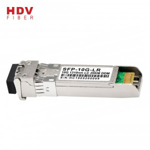
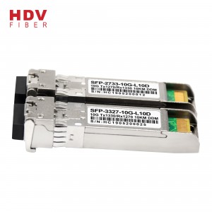
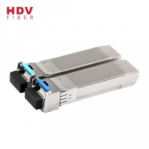
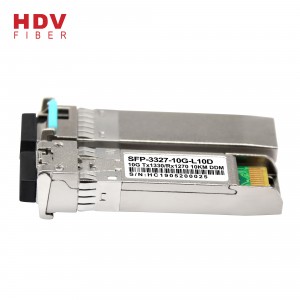
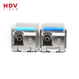
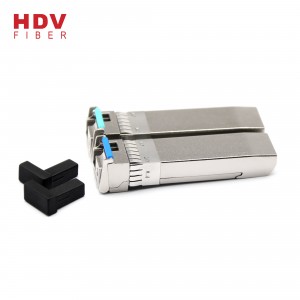
10g bidi sfp 10km 1330 1270 optical fiber transceiver sfp module
10GBASE-LW at 9.95Gbps
0.6~10Gb/s CPRI/OBSAI
Other Optical Link
|
Parameter |
Symbol |
Min |
Max |
Unit |
|
|
Storage Temperature |
TS |
-40 |
+85 |
℃ |
|
|
Operating Temperature |
TOP |
Commercial level |
-20 |
+70 |
℃ |
|
industrial level |
-40 |
85 |
|||
|
Supply Voltage |
VCC |
-0.5 |
+3.6 |
V |
|
|
Voltage on Any Pin |
VIN |
0 |
VCC |
V |
|
|
Soldering Temperature ,Time |
- |
260℃, 10 S |
℃,S |
||
|
Parameter |
Symbol |
Min. |
Typ |
Max. |
Unit |
|
|
Ambient Temperature |
TAMB |
Commercial level |
0 |
- |
70 |
℃ |
|
industrial level |
-40 |
85 |
||||
|
Power Supply Voltage |
V CC-VEE |
3.15 |
3.3 |
3.45 |
V |
|
|
Power Dissipation |
1 |
W |
||||
|
Data Rate |
10GBASE-LR |
10.3125 |
Gbps |
|||
|
Parameter |
Symbol |
Min. |
Typ. |
Max. |
Units |
||||
|
Transmitter Section |
|||||||||
| Center Wavelength |
lo |
1260 |
1270 |
1280 |
nm |
||||
|
1320 |
1330 |
1340 |
|||||||
| RMS Spectral Width |
Dl |
- |
- |
1 |
nm |
||||
| Side Mode Suppression Ratio |
SMSR |
30 |
dB |
||||||
| AverageOutput Power | 10km |
Po |
-5 |
- |
0 |
dBm |
|||
| 20km |
-2 |
+3 |
|||||||
| 40km |
+1 |
+5 |
|||||||
| 60km |
+1 |
+6 |
|||||||
| Extinction Ratio |
Er |
3.5 |
- |
- |
dB |
||||
| Dispersion Penalty |
2 |
dB |
|||||||
| Input Differential Impedance |
Zin |
90 |
100 |
110 |
Ω |
||||
| Relative Intensity Noise |
RIN12OMA |
-128 |
dB/Hz |
||||||
| Total jitter |
Tj |
0.28 |
UI(p-p) |
||||||
|
Receiver Section |
|||||||||
| Center Wavelength |
lo |
1320 |
1330 |
1340 |
nm |
||||
|
1260 |
1270 |
1280 |
|||||||
|
Receiver Sensitivity |
10km |
Rsen |
-14 |
dBm |
|||||
| 20km |
-14 |
||||||||
| 40km |
-17 |
||||||||
| 60km APD |
-23 |
||||||||
|
Receiver Overload |
0~40km |
Rov |
0.5 |
dBm |
|||||
| 60KM |
-6 |
||||||||
| Return Loss |
12 |
dB |
|||||||
| LOS Assert |
LOSA |
-25 |
dBm |
||||||
| LOS Dessert |
LOSD |
-15 |
dBm |
||||||
| LOS Hysteresis |
0.5 |
4 |
dB |
||||||
| LOS | High |
2.0 |
VCC+0.3 |
V |
|||||
| Low |
0 |
0.8 |
|||||||
|
Parameter |
Symbol |
Min. |
Typ. |
Max. |
unit |
|
|
Transmitter Section |
||||||
| Input Differential Impendence |
Zin |
90 |
100 |
110 |
Ohm |
|
| Data Input Swing Differential |
Vin |
180 |
700 |
mV |
||
| TX Disable | Disable |
2.0 |
Vcc |
V |
||
| Enable |
0 |
0.8 |
V |
|||
| TX Fault | Assert |
2.0 |
Vcc |
V |
||
| Deassert |
0 |
0.8 |
V |
|||
|
ReceiverSection |
||||||
| Output differential impendence |
Zout |
100 |
Ohm |
|||
| Data output Swing Differential |
Vout |
300 |
800 |
mV |
||
| Rx_LOS | Assert |
2.0 |
Vcc |
V |
||
| Deassert |
0 |
0.8 |
V |
|||
|
Parameter |
Range |
Accuracy |
Unit |
Calibration |
| Temperature |
-5~75 |
±3 |
ºC |
Internal |
| Voltage |
0~VCC |
0.1 |
V |
Internal |
| Bias Current |
0~12 |
0.3 |
mA |
Internal |
| Tx Power |
-8 ~1 |
±1 |
dBm |
Internal |
| Rx Power |
-18 ~0 |
±1 |
dBm |
Internal |
|
Addr |
Field Size (Bytes) |
Name of Field |
HEX |
Description |
| 0 |
1 |
Identifier |
03 |
SFP |
| 1 |
1 |
Ext. Identifier |
04 |
MOD4 |
| 2 |
1 |
Connector |
07 |
LC |
| 3-10 |
8 |
Transceiver |
10 00 00 00 00 00 00 00 |
Transmitter Code |
| 11 |
1 |
Encoding |
06 |
64B66B |
| 12 |
1 |
BR, nominal |
67 |
10000M bps |
| 13 |
1 |
Reserved |
00 |
|
| 14 |
1 |
Length (9um)-km |
00 |
|
| 15 |
1 |
Length (9um) |
00 |
|
| 16 |
1 |
Length (50um) |
08 |
|
| 17 |
1 |
Length (62.5um) |
02 |
|
| 18 |
1 |
Length (copper) |
00 |
|
| 19 |
1 |
Reserved |
00 |
|
| 20-35 |
16 |
Vendor name |
48 44 56 20 20 20 20 20 20 20 20 20 20 20 20 20 |
HDV |
| 36 |
1 |
Reserved |
00 |
|
| 37-39 |
3 |
Vendor OUI |
00 00 00 |
|
| 40-55 |
16 |
Vendor PN |
xx xx xx xx xx xx xx xx xx xx xx xx xx xx xx xx |
ASC II |
| 56-59 |
4 |
Vendor rev |
31 2E 30 20 |
V1.0 |
| 60-61 |
2 |
Wavelength |
05 1E |
1310nm |
| 62 |
1 |
Reserved |
00 |
|
| 63 |
1 |
CC BASE |
XX |
Check sum of byte 0~62 |
| 64-65 |
2 |
Options |
00 1A |
LOS, TX_DISABLE, TX_FAULT |
| 66 |
1 |
BR, max |
00 |
|
| 67 |
1 |
BR, min |
00 |
|
| 68-83 |
16 |
Vendor SN |
00 00 00 00 00 00 00 00 00 00 00 00 00 00 00 00 |
Unspecified |
| 84-91 |
8 |
Vendor date code |
XX XX XX 20 |
Year, Month, Day |
| 92-94 |
3 |
Reserved |
00 |
|
| 95 |
1 |
CC_EXT |
XX |
Check sum of byte 64~94 |
| 96-255 |
160 |
Vendor specific |
| Pins | Name |
Discription |
NOTE |
|
1 |
VeeT |
Transmitter Ground |
|
|
2 |
Tx Fault |
Transmitter Fault Indication |
1 |
|
3 |
Tx Disable |
Transmitter Disable |
2 |
|
4 |
MOD DEF2 |
Module Definition 2 |
3 |
|
5 |
MOD DEF1 |
Module Definition 1 |
3 |
|
6 |
MOD DEF0 |
Module Definition 0 |
3 |
|
7 |
RS0 |
Not Connected |
|
|
8 |
LOS |
Loss of Signal |
4 |
|
9 |
RS1 |
Not Connected |
|
|
10 |
VeeR |
Receiver Ground |
|
|
11 |
VeeR |
Receiver Ground |
|
|
12 |
RD- |
Inv. Received Data Output |
5 |
|
13 |
RD+ |
IReceived Data Output |
5 |
|
14 |
VeeR |
Receiver Ground |
|
|
15 |
VccR |
Receiver Power |
|
|
16 |
VccT |
Transmitter Power |
|
|
17 |
VeeT |
Transmitter Ground |
|
|
18 |
TD+ |
Transmit Data Input |
6 |
|
19 |
TD- |
Inv. Transmit Data Input |
6 |
|
20 |
VeeT |
Transmitter Ground |
(>0.8V, <2.0V): Undefined
High (2.0~3.465V): Transmitter Disabled
Open: Transmitter Disabled
3. MOD-DEF 0,1,2 are the module definition pins. They should be pulled up with a 4.7k~10kΩ resistor on
the host board. The pull-up voltage shall be VccT or VccR.
MOD-DEF 0 is grounded by the module to indicate that the module is present
MOD-DEF 1 is the clock line of two wire serial interface for serial ID
MOD-DEF 2 is the data line of two wire serial interface for serial ID
4. LOS is an open collector output, which should be pulled up with a 4.7k~10kΩ resistor on the host board to a voltage
6. These are the differential transmitter inputs. They are AC-coupled, differential lines with 100Ω differential termination inside the module.
|
Part No. |
Wavelength |
Connector |
Temp. |
TX Power (dBm) |
RX Sens (Max.) (dBm) |
Distance |
|
BSFP+-10G-L10A |
1270TX/1330RX |
LC |
0~70°C |
-5to0 |
-14 |
10km |
|
BSFP+-10G-L10B |
1330TX/1270RX |
LC |
0~70°C |
-5to0 |
-14 |
10km |
|
BSFP+-10G-L20A |
1270TX/1330RX |
LC |
0~70°C |
-2to3 |
-14 |
20km |
|
BSFP+-10G-L20B |
1330TX/1270RX |
LC |
0~70°C |
-2to3 |
-14 |
20km |
|
BSFP+-10G-L40A |
1270TX/1330RX |
LC |
0~70°C |
+1to+5 |
-17 |
40km |
|
BSFP+-10G-L40B |
1330TX/1270RX |
LC |
0~70°C |
+1to+5 |
-17 |
40km |
|
BSFP+-10G-L60A |
1270TX/1330RX |
LC |
0~70°C |
+1to+6 |
-20 |
60km |
|
BSFP+-10G-L60B |
1330TX/1270RX |
LC |
0~70°C |
+1to+6 |
-20 |
60km |
在线联系供应商
Other supplier products
| 深圳工厂FTTH 华为WIFI Onu 1GE+1FE+WIFI GPON ONT ONU XPON | 产品介绍 1. 概况 * HUR2202XR被设计为不同FTTH解决方案中的HGU(家庭网关单元)。运营商级FTTH应用提供不同的业务接入。 * HUR2202XR是基于成熟稳定、性价比高的XPON技术。 * HUR2202XR采用高可靠性、易管理、配置灵活、服务质量好的保证,满足中国电信C... | |
| New Promotion Fusion Splicing Machine Automatic Handheld Fusion Splicer | Technical Specifications Appicable Fibers SM(ITU-T G. 652&G.657),MM(ITU-T G.651),DS(ITU-T G.653),NZDS(ITU-T G655) ... | |
| Best Sell Mini 16 Port PON EPON OLT GEPON OLT Optic Fiber Equipment Optical Line Terminal for FTTH Solution | Product Specification: Service Features: Item EPON OLT 4/8/16PON PON Features IEEE 802.3ah EPONChina Telecom/Unicom EP... | |
| HDV 10 100base 4rj45 4 port fiber optic media converter HDV 10 100base 4rj45 4 port fiber optic media converter HDV 10 100base 4rj45 4 port fiber optic media converter HDV 10 100base 4rj45 4 port fib | Specifications: Model ZX-1M4WS33OC-M Product Fast Ethernet4+1 Switch Fixed Port 4*10/100Base–TX... | |
| 100M 8 port reverse power supply RPOE POE switch Reverse poe switch | PRODUCT FEATURE: REVERSE POE TECHNOLOGY:8 Port 10/100 Reverse POE switch which has latest generation of fast Ethernet reverse POE switching techno... |
Same products
| BLIIOT BL192Pro MQTT/Modbus TCP/OPC UA 边缘 I/O 模块 | 卖方: 深圳市钡铼技术有限公司 | BL192Pro 是一款灵活的边缘 I/O 模块,专为工业物联网应用而设计。它允许用户根据需要组合 1 至 3 个 Y 系列 I/O 板卡,其模块化设计可适应各种自动化场景。它支持 Modbus... | |
| X 波段8至12GHz 嵌入式环形器 带线环形器 | 卖方: UIY INC | 8至12GHz嵌入式环形器 带线环形器 设计特点 提供双节或多节设计,增强隔离性能。 以极具竞争力的价格实现卓越射频性能。 适用于军事、航天及商业应用。 可按需求定制设计。 ... | |
| cooling tower fills manufacturer | 卖方: 0000 | cooling tower fills manufacturer We are cooling tower fills manufacturer supplier! Welcome ... | |
| GRP water tanks | 卖方: 0000 | GRP water tanks is the abbreviation of Fiberglass Reinforced Plastic water tanks,are leading... | |
| cooling tower fills manufacturer | 卖方: 0000 | cooling tower fills manufacturer In the realm of industrial cooling, where efficiency is par... |


