Defense drone system
Product manual
1、System Introduce
1 The full-band jammer is based on the digital full- band fast frequency technology. It uses multi-octave antenna technology, broadband power amplifier technology, and fast directional counter-drone drone jammer , which can effectively respond to various modified drones The threat. At the same time, in order to meet the characteristics of both military and civilian use, the equipment is capable of rapid movement and can adapt to rapid land mobile
。
- Product technical indicators.
Full band jammer specification
|
Serial |
Name |
Main indicator |
marks |
|
1 |
Working frequency |
70MHz-6000MHz |
|
|
2 |
Anti method |
Radio interference |
|
|
3 |
Jammer method |
Individually controllable and definable |
|
|
4 |
Max width |
175MHz |
|
|
5 |
Polarization method: |
Vertical polarization |
|
|
6 |
Transmit power |
≤42dBm |
|
|
7 |
Installation method |
Fixed |
|
|
8 |
Tracking accuracy |
||
|
9 |
Airspace coverage |
90°(pitch ) 360°(horizontal) |
|
|
10 |
Anti distance |
|
|
|
11 |
Weight |
80kg |
|
|
12 |
interface |
100M Ethernet |
|
|
13 |
Power supply |
220V/AC |
|
|
14 |
Power consumption |
≤2100w |
2 product composition, structure and working principle
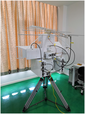
3 2.1 Product composition
|
Serial |
Name |
part |
Qty |
Installation location |
|
1 |
Antenna |
Log-periodic antenna70MHz-1GHz) |
1 |
Antenna frame top |
|
Broadband Horn Antenna (1GHz-2GHz) |
1 |
Front of antenna frame |
||
|
Broadband Horn Antenna (2GHz-4GHz) |
1 |
Antenna frame left |
||
|
Broadband Horn Antenna (4GHz-6GHz) |
1 |
Antenna frame right |
||
|
2 |
Jammer |
2 |
One on each side of the turntable |
|
|
3 |
Turntable |
1 |
On tripod |
|
|
4 |
Antenna frame |
1 |
Turntable top |
|
|
tripod |
1 |
level ground |
||
|
RF cable |
5 |
Connect the interference host to the antenna |
||
|
Power cable |
1 |
Power connector on the bottom of the turntable |
||
|
cable |
1 |
Network interface at the bottom of the turntable |
||
|
5 |
Software |
1 |
||
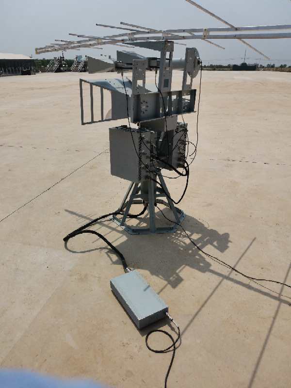
3 Product shape
See the picture :
The jammer uses multiple autonomous interference source architectures to achieve full coverage and effective countermeasures for frequencies in the range of 70MHz-6000MHz. The system's working process is divided into 4 sections, namely 70MHz-1000MHz, 1000MHz-2000MHz, 2000MHz-4000MHz, 4000MHz-6000MHz and other four parts. It can work in time-sharing and has the ability to work simultaneously. Its maximum interference bandwidth is 175MHz, and the bandwidth can be Tune. Through the fast frequency hopping mode of not less than 40,000 hops / s, the interference signal is separated and the bandwidth is extended.
According to the actual deployment needs, you can choose to deploy one or several devices to work together according to the specific protection scope and the importance of the protection. In an open and unobstructed environment, a jammer can effectively protect an area with a radius of not less than 5Km. After the system equipment is deployed at the corresponding location, it can work with the detector system 24 hours a day. After the radar or radio detection equipment detects or orients the surrounding UAV, the central control software sends the corresponding control instructions to the jammer, and the jammer is turned to the corresponding angle and the jammer is turned on.
The jammer uses multiple independent interference sources to achieve flexible interference to the frequency in the range of 70MHz-6000MHz, flexible adjustment of interference power, and flexible and variable interference patterns. The system's working process is divided into 4 sections, namely 100MHz-1000MHz, 1000MHz-2000MHz, 2000MHz-4000MHz, 4000MHz-6000MHz and other four parts. It can work at the same time and has the ability to work at the same time. Fast frequency hopping is not less than 40,000 hops / s.
1 Alleged Data Link Interference Effectiveness Evaluation
The control data link of the drone often adopts a low data rate and strong anti-interference ability modulation method and frequency hopping pattern, which is essentially digital modulation communication. According to the basic technical specifications of the target drone, combined with the bit error rate characteristics required for the demodulation of the alleged signal, the SNR required for its demodulation needs to be 10-12dB as the basic standard. The interference power should not be low without considering the spread-spectrum gain. Below 10dB of communication power, if the spread spectrum communication method is considered in the communication process, the spread spectrum gain should be considered.
The interference power is 100w (average 43dBm) considering the saturation power amplifier's ability to amplify the peak-to-average ratio signal (6dB peak-to-average ratio), the antenna gain is 13dBi, the transmission loss is 1dB, and the polarization loss is 3dB. The relationship between the interference signal and communication signal received at the receiving end with different distances is shown in the following figure (Figure 2):
:
Figure 2.Relationship between interference signals and communication signals as a function of distance
Figure 3 Effect of signal-to-noise ratio on bit error rate under different demodulation methods
It can be analyzed from the above figure that it is capable of achieving 30km @ (dry-to-ratio 2: 1, GFSK), 10km @ (micro drone, ERIP = 20dBm, 10-to-1 dry-ratio, OFDM- DS) the ability to interfere.
2 Navigation Signal Interference Effectiveness Evaluation
Civilian drones generally use GPS navigation equipment as the main navigation method, and use the GPS L1 frequency band as the main navigation frequency band. Considering that the drone's on-board navigation equipment may use GPS P code for navigation, it is necessary to set C on the L1 frequency band. The performance of the / A code and the P code is comprehensively considered. Considering that the effective broadcast of one piece of data for GPS, whether C / A code or P code, is 50bps, under the condition of C / A code, its chip rate is 1.023Mbps. In general, the spreading gain is 43.1dB, and the effective spreading gain of the P code is 53.1dB. Considering that the received power of the GPS navigation signal to the ground is generally around -128.5dBm, the relative power is about -85.4dBm (C / A code) and -75.4dBm (P code) when the spread-spectrum-related gain is added.
The interference power is 100w (average 43dBm), considering the saturation power amplifier's ability to amplify the peak-to-average ratio signal (6dB peak-to-average ratio), the antenna gain is 13dBi, the transmission loss is 1dB, and the polarization loss is 3dB. The relationship between the interference signal and communication signal received at the receiving end with different distances is shown in the following figure:
Figure 4 Relation power diagram
It can be clearly seen from the figure that the C / A and P codes have interference capabilities above 30km.
Send product request
Other supplier products
| J14 series electrical connector | ||
| Defense drone system | Product manual 1、System Introduce 1 The full-band jammer is based on the digital full- band fast frequency technology. It uses multi-octave antenna... | |
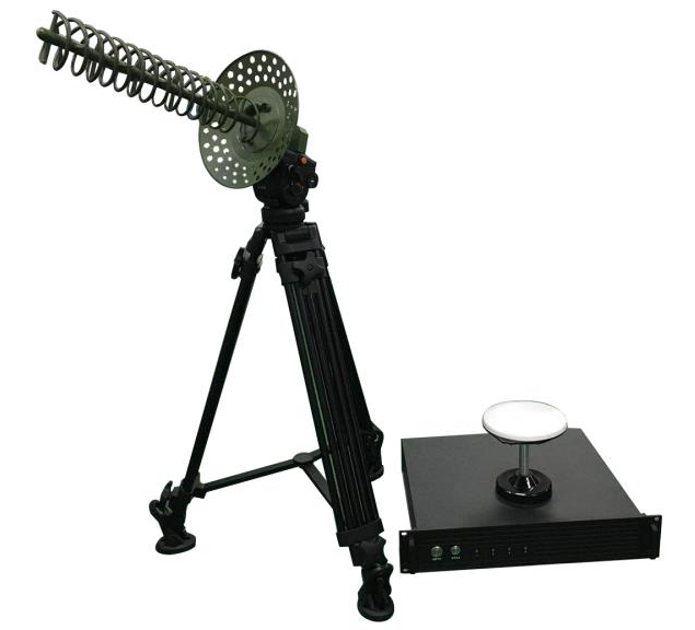
| Defense drone system | The drone satellite navigation decoy system uses the most advanced satellite navigation technology in China to control drone. Through transmitting ... |
Same products
| Carbon Steel Bridge Guardrail | Seller: Wuhan Dachu Traffic Facilities Co., Ltd | Carbon steel bridgeguardrailis an important safety feature that can prevent vehicles from running... | |
| Customized Thrie-Beam Highway Guardrail | Seller: Wuhan Dachu Traffic Facilities Co., Ltd | Customized Thrie-Beam Highway Guardrailmay include the size and shape of the beams, the spacing b... | |
| Non Blocked MASH-TL3 Single Steel Guardrail | Seller: Wuhan Dachu Traffic Facilities Co., Ltd | DACHU guardrailis manufactured to AASHTO specifications in M180 Class A or B, and finish types 1,... | |
| Hot Dip Galvanized W-Beam Guardrail | Seller: Wuhan Dachu Traffic Facilities Co., Ltd | hot dip galvanized w-beam guardrailis cost-effective highway barriers designed to reduce the coll... | |
| S355JR Steel W Beam Road Crash Barrier | Seller: Wuhan Dachu Traffic Facilities Co., Ltd | This hot-dip galvanized steel W beamis one of the highway safety products from DACHUconforms to A... |


