HSG Engineering Hydraulic Cylinders
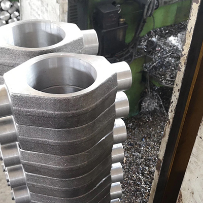
Founded in 2000, JC, large hydraulic cylinder manufacturers,forging is a forged components manufacturerof forged metal products. The company's main product is die mold forging parts, including but not limited to forged hydraulic cylinder bottoms, forged hydraulic cylinder end cap, forged hydraulic cylinder earring, and forged clevis, forged trunnions and other custom forged parts.
What is HSG Engineering Hydraulic Cylinder?
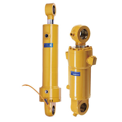
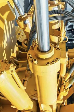
HSG type engineering hydraulic cylinder is a double-acting single-rod piston type hydraulic cylinder. It has the characteristics of simple structure, reliable operation, convenient assembly and disassembly, easy maintenance, buffering device and various connection methods. Mainly used in construction machinery, transportation, ships, lifting machinery, mining, machinery.
Advantages of HSG Engineering Hydraulic Cylinder:
The HSG series engineering hydraulic cylinder is a double-acting single-piston rod hydraulic cylinder; the mounting method is mostly ear-ring type. There are three types of external connection: internal key connection and flange connection according to the connection method of the cylinder head and the cylinder. Engineering hydraulic cylinders are mainly used in hydraulic systems such as construction machinery, heavy machinery, lifting machinery and mining machinery.
Product Description
Front and Rear Earrings Installation Features of HSG Engineering Hydraulic Cylinder
The tail single earring is suitable for the single earring installation condition required for the path condition or structural design of the piston rod to be along the path of the same motion plane when the piston rod is moving along the same motion plane; It is possible to install the tail and rod end spherical bearings at this time, but pay attention to the pressure load that the spherical bearing is allowed to bear.
HSG double-acting single-rod piston type hydraulic cylinder is mainly composed of a cylinder tube, a piston, a piston rod, a cylinder head, a cylinder bottom, a piston rod head and related auxiliary devices. The piston divides the cylinder into two left and right chambers. By means of the action of the pressure oil, the cylinder reciprocates. In order to improve its working effect, a sealing ring is arranged on the piston to eliminate internal leakage. Where the piston rod passes through the cylinder head, due to the existence of the gap, the external leakage phenomenon is easy to occur, and the dust can enter the cylinder through the gap, so the sealing device and the dustproof factor are set. At the same time, in order to eliminate the influence of the eccentric load on the piston operation All hydraulic cylinders must be placed at the protruding end of the piston rod, and a guiding sleeve of a considerable length is provided. In addition, when the piston moves at a faster speed, the mechanical collision between the piston and the cylinder bottom and the cylinder head is serious, so the hydraulic cylinder at both ends, a buffer reduction gear should be provided.
Model Coding:
① Unit code
②Connecting type L: Screw K: Clasp F: Flange
③ Bore/Rod (mm)
④ Pressure E: 16MPa F: 20MPa G: 25MPa
⑤ Mounting
⑥ Connecting in rod
⑦ Oil port 1: Screw 2: Flange
⑧ Stroke (mm)
⑨ Mounting distance
Technical Specification:
Specifications: Mark* is for speed ratio 1.64 only.
|
Bore D |
Φ |
d |
d1 |
R |
b |
L6 |
M2 |
L10 |
L5 |
L7 |
L2 |
2-M1 |
H1 |
Φ1 |
||||
|
pressure |
speed ratio |
|||||||||||||||||
|
16 |
20 |
25 |
2(1.64) |
|||||||||||||||
|
32 |
42 |
48 |
16 |
18 |
*20 |
16/GE6ES |
20 |
18 |
20 |
40 |
40 |
50 |
245 |
15 |
50 |
|||
|
40 |
50 |
56 |
20 |
22 |
25 |
20/GE20ES |
25 |
30 |
50 |
30 |
65 |
255 |
65 |
|||||
|
50 |
65 |
68 |
25 |
28 |
32 |
30/GE30ES |
35 |
40 |
60 |
40 |
280 |
75 |
||||||
|
63 |
78 |
80 |
83 |
32 |
35 |
45 |
65 |
295 |
79 |
|||||||||
|
80 |
95 |
102 |
40 |
45 |
55 |
40/GE40ES |
45 |
50 |
80 |
50 |
70 |
347 |
18 |
110 |
||||
|
90 |
108 |
114 |
45 |
50 |
63 |
M36X2 |
90 |
66 |
357 |
|||||||||
|
100 |
118 |
127 |
50 |
55 |
70 |
50/GE50ES |
60 |
65 |
M42X2 |
110 |
60 |
72 |
402 |
M27X2 |
20 |
|||
|
110 |
130 |
133 |
140 |
55 |
63 |
80 |
M48X2 |
115 |
77 |
422 |
||||||||
|
125 |
145 |
152 |
63 |
70 |
90 |
M52X2 |
140 |
78 |
452 |
|||||||||
|
140 |
164 |
168 |
70 |
80 |
100 |
60/GE60ES |
70 |
75 |
M60X2 |
155 |
70 |
85 |
498 |
|||||
|
150 |
180 |
75 |
85 |
105 |
M64X2 |
160 |
75 |
92 |
513 |
M33X2 |
22 |
|||||||
|
160 |
194 |
80 |
90 |
110 |
M68X2 |
170 |
80 |
100 |
533 |
|||||||||
|
180 |
219 |
90 |
100 |
125 |
70/GE70ES |
80 |
85 |
M76X2 |
190 |
89 |
107 |
588 |
M42X2 |
24 |
||||
|
200 |
245 |
100 |
110 |
140 |
80/GE80ES |
95 |
90 |
95 |
M85X2 |
210 |
100 |
110 |
628 |
|||||
|
220 |
273 |
110 |
125 |
160 |
90/GE90ES |
105 |
100 |
105 |
M95X2 |
220 |
110 |
120 |
658 |
25 |
||||
|
250 |
299 |
125 |
140 |
180 |
100/GE100ES |
120 |
110 |
120 |
M105X2 |
255 |
122 |
135 |
688 |
|||||
|
Bore D |
rod |
pressure 16Mpa |
|||||
|
speed ratio |
Pushing force(KN) |
pull force(KN) |
|||||
|
2(1.64) |
speed ratio=1.33 |
speed ratio=1.46 |
speed ratio=2(1.64) |
||||
|
32 |
16 |
18 |
*20 |
*7.8 |
|||
|
40 |
20 |
22 |
25 |
||||
|
50 |
25 |
28 |
32 |
||||
|
63 |
32 |
35 |
45 |
||||
|
80 |
40 |
45 |
55 |
||||
|
90 |
45 |
50 |
63 |
||||
|
100 |
50 |
55 |
70 |
||||
|
110 |
55 |
63 |
80 |
||||
|
125 |
63 |
70 |
90 |
||||
|
140 |
70 |
80 |
100 |
||||
|
150 |
75 |
85 |
105 |
||||
|
160 |
80 |
90 |
110 |
||||
|
180 |
90 |
100 |
124 |
||||
|
200 |
100 |
110 |
140 |
||||
|
220 |
110 |
125 |
160 |
||||
|
250 |
125 |
140 |
180 |
||||
|
Mounting |
||
|
Code |
Mounting |
Notice |
|
1 |
single articulated clevis( with bush) |
|
|
2 |
single articulated clevis( with oscillating bearing) |
|
|
3 |
middle trunnion |
Bore ≥80 |
|
4 |
front flange |
Bore ≥80 |
|
5 |
middle flange |
Bore ≥80 |
|
Piston rod connecting |
||
|
Code |
Mounting |
Notice |
|
1 |
outside screw |
|
|
2 |
outside screw and articulated clevis( with bush) |
|
|
3 |
outside screw and articulated clevis( with oscillating bearing) |
|
|
4 |
one piece single articulated clevis( with bush) |
|
|
5 |
one piece single articulated clevis( with oscillating bearing) |
|
Specifications:
Mark* is for speed ratio 1.64 only.
|
Bore D |
Φ |
d |
d1 |
R |
b |
L6 |
M2 |
L10 |
L5 |
L7 |
L2 |
2-M1 |
H1 |
Φ1 |
||||
|
pressure |
speed ratio |
|||||||||||||||||
|
16 |
20 |
25 |
2(1.64) |
|||||||||||||||
|
32 |
42 |
48 |
16 |
18 |
*20 |
16/GE6ES |
20 |
18 |
20 |
40 |
40 |
50 |
245 |
15 |
50 |
|||
|
40 |
50 |
56 |
20 |
22 |
25 |
20/GE20ES |
25 |
30 |
50 |
30 |
65 |
255 |
65 |
|||||
|
50 |
65 |
68 |
25 |
28 |
32 |
30/GE30ES |
35 |
40 |
60 |
40 |
280 |
75 |
||||||
|
63 |
78 |
80 |
83 |
32 |
35 |
45 |
65 |
295 |
79 |
|||||||||
|
80 |
95 |
102 |
40 |
45 |
55 |
40/GE40ES |
45 |
50 |
80 |
50 |
70 |
347 |
18 |
110 |
||||
|
90 |
108 |
114 |
45 |
50 |
63 |
M36X2 |
90 |
66 |
357 |
|||||||||
|
100 |
118 |
127 |
50 |
55 |
70 |
50/GE50ES |
60 |
65 |
M42X2 |
110 |
60 |
72 |
402 |
M27X2 |
20 |
|||
|
110 |
130 |
133 |
140 |
55 |
63 |
80 |
M48X2 |
115 |
77 |
422 |
||||||||
|
125 |
145 |
152 |
63 |
70 |
90 |
M52X2 |
140 |
78 |
452 |
|||||||||
|
140 |
164 |
168 |
70 |
80 |
100 |
60/GE60ES |
70 |
75 |
M60X2 |
155 |
70 |
85 |
498 |
|||||
|
150 |
180 |
75 |
85 |
105 |
M64X2 |
160 |
75 |
92 |
513 |
M33X2 |
22 |
|||||||
|
160 |
194 |
80 |
90 |
110 |
M68X2 |
170 |
80 |
100 |
533 |
|||||||||
|
180 |
219 |
90 |
100 |
125 |
70/GE70ES |
80 |
85 |
M76X2 |
190 |
89 |
107 |
588 |
M42X2 |
24 |
||||
|
200 |
245 |
100 |
110 |
140 |
80/GE80ES |
95 |
90 |
95 |
M85X2 |
210 |
100 |
110 |
628 |
|||||
|
220 |
273 |
110 |
125 |
160 |
90/GE90ES |
105 |
100 |
105 |
M95X2 |
220 |
110 |
120 |
658 |
25 |
||||
|
250 |
299 |
125 |
140 |
180 |
100/GE100ES |
120 |
110 |
120 |
M105X2 |
255 |
122 |
135 |
688 |
|||||
|
Bore D |
rod |
pressure 16Mpa |
|||||
|
speed ratio |
Pushing force(KN) |
pull force(KN) |
|||||
|
2(1.64) |
speed ratio=1.33 |
speed ratio=1.46 |
speed ratio=2(1.64) |
||||
|
32 |
16 |
18 |
*20 |
*7.8 |
|||
|
40 |
20 |
22 |
25 |
||||
|
50 |
25 |
28 |
32 |
||||
|
63 |
32 |
35 |
45 |
||||
|
80 |
40 |
45 |
55 |
||||
|
90 |
45 |
50 |
63 |
||||
|
100 |
50 |
55 |
70 |
||||
|
110 |
55 |
63 |
80 |
||||
|
125 |
63 |
70 |
90 |
||||
|
140 |
70 |
80 |
100 |
||||
|
150 |
75 |
85 |
105 |
||||
|
160 |
80 |
90 |
110 |
||||
|
180 |
90 |
100 |
124 |
||||
|
200 |
100 |
110 |
140 |
||||
|
220 |
110 |
125 |
160 |
||||
|
250 |
125 |
140 |
180 |
||||
|
Mounting |
||
|
Code |
Mounting |
Notice |
|
1 |
single articulated clevis( with bush) |
|
|
2 |
single articulated clevis( with oscillating bearing) |
|
|
3 |
middle trunnion |
Bore ≥80 |
|
4 |
front flange |
Bore ≥80 |
|
5 |
middle flange |
Bore ≥80 |
|
Piston rod connecting |
||
|
Code |
Mounting |
Notice |
|
1 |
outside screw |
|
|
2 |
outside screw and articulated clevis( with bush) |
|
|
3 |
outside screw and articulated clevis( with oscillating bearing) |
|
|
4 |
one piece single articulated clevis( with bush) |
|
|
5 |
one piece single articulated clevis( with oscillating bearing) |
|
We provide double acting telescopic hydraulic cylinders for sale, engine lift hydraulic cylinder, biggest hydraulic cylinder, double acting hydraulic cylinder types, and so on. And now the double acting hydraulic cylinder priceis relatively cheap.
在线联系供应商
Other supplier products
| Forged Trunnion | Product: forged trunnion Application: hydraulic cylinder, truck Place of origin: Hebei, China (Mainland) Material: C45, 20, ASTM A216 70-36 grade W... | |
| BM1 Small Hydraulic Motor | We have small hydraulic motors for sale! Brief Introduction: The BM1 is a small, spool valve type small hydraulic wheel motor. Its characterist... | |
| Forklift Series Cylinders | Forklift Series Cylinders What is Forklift Series Cylinder? The forklift hydraulic lift cylinder include tilt cylinders, lift cylinders, steering c... | |
| Hydraulic Cylinder | Large Hydraulic Cylinders for Sale Hydraulic cylinder is an actuator that converts hydraulic energy into mechanical energy and performs linear reci... | |
| BM3 Cycloid Hydraulic Motor | Brief Introduction: The BM3 cycloid hydraulic motoris a shaft-loaded cycloidal hydraulic motor with higher load capacity and can be used for lon... |
Same products
| YC160W Wheel excavator YC160W | 卖方: Guangxi Yuchai Equipment Technology Co., Ltd | YC160W Wheel excavator YC160W wheel excavator is a new generation of full hydraulic wheel excavat... | |
| Yuchai U20 mini excavator | 卖方: Guangxi Yuchai Equipment Technology Co., Ltd | Yuchai U20 mini excavator Improvements in Over 80 Details: Tailless Excavator U20 is a Yuchai ... | |
| Yuchai YC80 small excavator | 卖方: Guangxi Yuchai Equipment Technology Co., Ltd | Yuchai YC80 small excavator International brand engine It is equipped with Yanmar 4TNV98C natur... | |
| Top Type Hydraulic Breaker | 卖方: Guangxi Yuchai Equipment Technology Co., Ltd | Top Type Hydraulic Breaker With the higher restriction of blasting control,hydraulic breakeris w... | |
| S35-Electric Skid Steer Loader | 卖方: Guangxi Yuchai Equipment Technology Co., Ltd | S35-Electric Skid Steer Loader Yuchai S35 Electric Skid Steer Loaderis compact and flexible, des... |


