
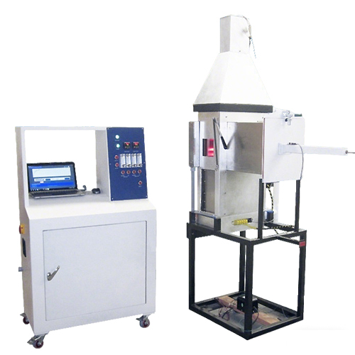
OSU Rate of Heat Release Apparatus,Fire safety heat release tester for building materials

Whats/App: +86 156 1874 6768
Web: standard-groups.com
The OSU Rate of Heat Release Apparatus is a precision instrument designed to measure the heat release rate (HRR) of materials, primarily for aerospace applications. Originally developed by Smith at Ohio State University in 1972. this apparatus has become an FAA-approved testing instrument for evaluating the combustion behavior of aircraft materials. You can use it to accurately determine heat release rates, flame spread, and smoke generation in compliance with international aviation safety standards, including FAR Part 25 Appendix F Part IV, Airbus AITM 2.0006. and Boeing BSS 7322. Its stainless-steel combustion chamber, PID-controlled heating system, and advanced data acquisition software enable reliable, reproducible results in a controlled laboratory environment.
Application
The OSU Rate of Heat Release Apparatus is widely used in the following areas:
Aerospace Material Testing: Assess heat release, flame spread, and smoke generation of aircraft cabin materials according to FAA, Airbus, and Boeing standards.
Aircraft Interior Compliance: Evaluate materials for FAR Part 25 Appendix F Part IV, ensuring cabin safety during fire scenarios.
Material Research & Development: Determine thermal degradation and combustion characteristics of plastics, composites, and coatings for aerospace applications.
Fire Safety Laboratory Testing: Integrate HRR data with flame spread and smoke density evaluations to support fire safety certification.
Typical test materials include aircraft cabin panels, interior plastics, textiles, laminates, and composite materials.
Standards
The apparatus supports compliance with the following standards:
BSS 7322 – Aerospace materials flame spread, smoke density, and toxicity evaluation.
AITM 2.0006 – Aerospace materials flame spread and smoke generation measurement.
FAR Part 25 Appendix F Part IV – Aircraft cabin material flame spread and smoke toxicity requirements.
GB/T 27904‑2011 – Flame spread performance of interior decoration materials (can be combined with HRR testing).
GB 8624‑2012 – Classification of combustion performance of building materials and products (can be combined with HRR results).
Parameters
| Parameter Category | Details |
|---|---|
| Dimensions | 760 mm (W) × 1850 mm (H) × 850 mm (D) |
| Weight | 218 kg |
| Combustion Chamber | Stainless steel with high-temperature glass viewing window |
| Heat Radiation Source | 4 Glowbar heating rods, up to 35 kW/m² flux |
| Temperature Control | 2 independent PID controllers |
| Power Supply | 220 V, 35 A |
| Operating Temperature | 10°C – 35°C |
| Combustion Gas | Methane |
| Auxiliary Gas | Constant temperature and flow air supply |
Features
Stainless-steel combustion chamber with high-temperature observation window.
Four Glowbar heating rods providing up to 35 kW/m² radiant heat flux.
Dual PID temperature controllers for precise heat regulation.
Fully automatic pneumatic sample feeding and shielded door system.
Upper stationary burner and movable lower burner for flexible testing.
Rotor flow meters for controlling upper and lower burner gas flow.
Movable T-shaped calibration burner and flow controller for system calibration.
Mass flow controllers automatically applied to thermopile calibration.
Water-cooled heat flux sensors for accurate measurement of irradiated heat.
Airflow temperature control system for constant temperature and flow within the test chamber.
Orifice flow meters to monitor flow rate and pressure entering the test chamber.
Integrated data acquisition system and standard HRR testing software.
Accessories
Water-cooled heat flux sensors
Pneumatic sample feeder and shielded door
Upper and lower burners with flow control
T-shaped calibration burner
Rotor and mass flow controllers
PID temperature controllers
Data acquisition hardware and HRR software
Test Procedures
Ensure installation space allows safe operation and access.
Connect the apparatus to a 220 V, 35 A power supply.
Provide constant-temperature, constant-flow auxiliary gas.
Connect methane as the combustion gas supply.
Mount the test sample in the combustion chamber.
Adjust Glowbar heating rods and set PID controllers to desired heat flux.
Activate the automatic sample feeder and shielded door system.
Ignite the sample and upper/lower burners.
Monitor heat release rate, temperature, and gas flow using the software interface.
Record data for HRR, flame spread, and smoke generation.
After testing, shut off gas supply and allow the chamber to cool before sample removal.
Maintenance Information
Inspect and clean the combustion chamber and viewing window regularly.
Check burners, gas lines, and flow meters before each test for leaks or blockage.
Calibrate heat flux sensors and PID controllers periodically to ensure accuracy.
Verify data acquisition system and HRR software functionality.
Replace worn or damaged safety interlocks and pneumatic components as needed.
在线联系供应商
Other supplier products
 |
Corrosion Test Apparatus IEC 60754 Part 1 & 2,Corrosion Test Chamber | Whats/App: +86 156 1874 6768 Web: standard-groups.com Description: This tester is used to test the acidity of the gas that released during combu... |
 |
Blood Bag Emptying under Pressure Tester | Whats/App: +86 156 1874 6768 Web: standard-groups.com The Blood Bag Emptying Under Pressure Tester is suitable for testing the pressurized emptyi... |
 |
Simulated Transport Vibration Test Machine | Whats/App: +86 156 1874 6768 Web: standard-groups.com Simulated Transport Vibration Testing Machines can be divided into two types: small-scale s... |
 |
Automotive Wire Adhesion Tester for quality control | Get a quote: Whats/App: +86 156 1874 6768 Web: standard-groups.com The Automotive Wire Adhesion Tester is designed to evaluate the bonding stren... |
 |
Vacuum Ball - Disk Friction Tester | Whats/App: +86 156 1874 6768 Web: standard-groups.com A vacuum ball-on-disk friction tester is a device used to simulate friction and wear behavi... |
Same products
 |
China factory electrode TGYS125 for power station Selection of advanced | 卖方: DONGFANG YOYIK (DEYANG) ENGNIEERING CO; LTD | "China factory electrode TGYS125 for power station Selection of advanced technology, absolutely f... |
 |
Laser Chuck | 卖方: 00000 | Laser Chuck Introduce foreign advanced technology and management concept, High precision pro... |
 |
Power Pallet Jack For Sale | 卖方: Jinan Hulk Machinery Co., Ltd | Power Pallet Jack For Sale Electric Pallet Truck For Sale As a supplier of power pallet jac... |
 |
Multi Directional Forklift For Sale | 卖方: Jinan Hulk Machinery Co., Ltd | Multi Directional Forklift For Sale Multi Directional Forklift For Sale As a supplier of mu... |
 |
Narrow Aisle Forklift For Sale | 卖方: Jinan Hulk Machinery Co., Ltd | Narrow Aisle Forklift For Sale Narrow Aisle Forklift For Sale As a supplier of , we provide... |
